by Russell Morrison
For modern-day users of 3-D measurement technology, a maze of unmanageable indoor and outdoor conditions presents headaches galore. Many portable metrology devices need near-laboratory conditions to provide accurate measurements. Environmental factors such as extreme temperatures, vibration and motion, line-of-sight obstructions and employee traffic are often presumed to be insurmountable conditions for those engaged in precision measurement.
But that conclusion is incorrect. Metrologists, engineers, surveyors, manufacturers, scientists and quality-control technicians are long-time users of digital photogrammetry for portable, in-place measurement of large objects. Photogrammetric surveys have been performed in arctic weather, tropical temperatures, 30-mile-per-hour winds, underwater venues, remote mountainous areas and at extremely high altitudes. In many cases, the inherent flexibility and versatility of digital photogrammetry make it the only technology capable of handling such formidable metrology ventures.
Photogrammetry is a three-dimensional coordinate measuring technique that uses photographs as the fundamental medium for metrology. The combination of an ultra-mobile photogrammetric camera and the high-precision measurement capabilities of a coordinate measuring machine (CMM) sets this technology apart from other portable CMMs.
Conventional uses of digital photogrammetry include in-place measurement of large parts and assemblies, tooling inspection and adjustment, test-retest measurement, deformation studies, part inspection, tamoana (disassembly and reassembly) studies and more. Photogrammetry is used by quality professionals working in diverse manufacturing industries such as aerospace, shipbuilding, automotive, antenna and satellites, space hardware and power generation.
This article surveys photogrammetry's most interesting challenges, compelling applications and a few extraordinary uses. But first, a quick review of photogrammetry basics.
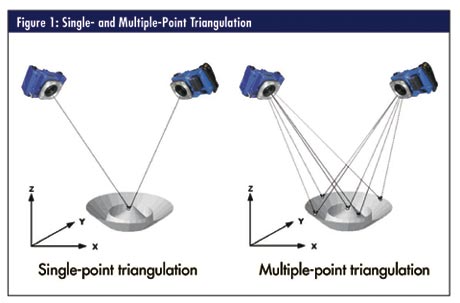
Triangulation is the fundamental principle used in photogrammetry. By taking photographs from at least two different locations, lines of sight can be developed from each camera to points on the object. These lines of sight, sometimes called "rays" due to their optical nature, are mathematically intersected to produce three-dimensional coordinates of the points of interest. Because photogrammetry measures by triangulation, in theory only two photographs are required for a measurement. However, at least four to six photographs are recommended because this range allows the camera to self-calibrate. That is, because the points being measured don't change, as more data are gathered on a point as measured from different angles, more is known about any inaccuracies in the camera itself. These inaccuracies can then be calibrated out of the result.
Measuring industrial objects with photogrammetry usually consists of the following steps:
• Planning the measurement
• Targeting the object
• Taking pictures
• Measuring pictures
• Processing pictures to obtain 3-D
coordinate data
• Analyzing the results
This list is merely a guide because every measurement project is unique.
There are many ways to capture points of interest on an object. Targeting is just one method used in close-range photogrammetry. The photogrammetry system measures special targets made of a thin, 0.1-mm-thick (0.004 in.), flat, grayish-colored retroreflective material, which returns light very efficiently to the light source. The photogrammetric camera doesn't measure the object directly but measures the center of the retroreflective target. By placing the targets on or in a known relationship to the points of interest, those points can be measured.
In some circumstances, it might be difficult to directly target the point you want to measure. Many different types of retroreflective targets have been developed to solve this problem. Sometimes, where it isn't possible to target a point, a hand-held probe with targets on it can be used. Because the geometry between the probe tip and targets are known, knowing where the targets are means you know the location of the probe tip, even if the tip isn't visible to the camera.
Once an object is targeted, or a targeted probe is in place, the camera is triggered and the camera's flash illuminates the targets to make an exposure independent of the ambient light level. This means that the object can be photographed in bright light or total darkness, and the target exposure will be the same. The target and object exposure are largely independent, because target exposure is provided by the strobe, and object exposure is provided by the ambient light. The camera automatically sets the shutter speed and flash power setting based on environment lighting conditions.
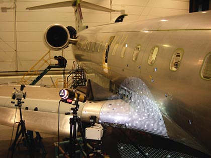
This photogrammetric setup uses retroreflective targets and a
stroboscopic light source to measure a wing section. Although targeting has been the mainstay in photogrammetry, new developments are giving metrology professionals alternatives to capture points of interest. PRO-SPOT, a stroboscopic light projector from Geodetic Systems Inc., is used with the company's V-STARS photogrammetry system to cast thousands of dots upon a large object's surface (e.g., an airplane) and measure them in less than one minute. This system generates fast, accurate, dense, noncontact measurements on large surfaces such as molds, master models, panels, antennas and other components.
Photogrammetry provides accuracies comparable to those achieved by other large-volume, high-accuracy portable coordinate measurement systems. Photogrammetric accuracy depends on several interdependent factors:
• Camera resolution
• Size of the measured object
• Number of photographs taken
• Geometric layout of the camera stations (i.e., camera locations) relative to the object and each other
As a rule of thumb, if you take six to eight photographs with good geometry, and each photograph sees the entire object, you should obtain accuracies of 25-50 µm (0.001 in.-0.002 in.) on a 15-foot object.
Part of photogrammetry's uniqueness is its ability to accurately measure large objects in adverse conditions. Photogrammetry has captured precision data on land, sea and air. The subjects of the following case studies have been objects both larger and smaller than a regulation football field. The aerospace and automotive industries have long been primary users of this technology, but metrology experts are also called upon for unusual or formidable measurement requests.
Steve Ihlenfeldt, CEO of ATT Metrology Services, owns a company that provides large-volume metrology services to the aerospace, shipbuilding and power-generation industries.
"We have more and more customers looking for high-precision measurement services to be conducted in environments that are very dynamic and not stable," explains Ihlenfeldt. "Photogrammetry is tailor-made for these types of jobs. A hand-held photogrammetric camera can photograph hundreds or even thousands of targets simultaneously in a few milliseconds. This means that both the camera and object can be in motion, and an extremely accurate measurement can still be obtained."
The interior or exterior of an aircraft isn't structurally sound enough to support or mount a traditional portable CMM, which requires a stable platform for accurate data capture. Stabilizing a large-volume object such as an aircraft to the extent necessary to obtain accurate measurements could require moving the aircraft indoors, jacking the aircraft and removing all the personnel on the plane. Typically, these options aren't acceptable to the manufacturer. A photogrammetry system is an ideal solution for such a situation.
ATT recently secured a contract to provide metrology services for measuring the large aircraft infrared countermeasures (LAIRCM) system on Boeing's C-17 cargo plane. The project requires measurement of the LAIRCM components using digital photogrammetry to determine their spatial relationship in the aircraft's tail cone section. Measurements are captured outdoors, at night, often in windy conditions in excess of 20 knots and with aircraft movement exceeding ± 2 in. ATT is able to target the aircraft, take digital photographs, process the results in a few hours and achieve accuracies better than a few thousandths of an inch.
The ADI Bushmaster is an all-terrain multifunction armored vehicle. Built for the Australian army, it's delivered in many configurations, ranging from frontline troo
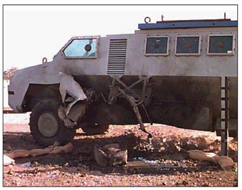
Bushmaster after mine detonation |
p carrier to mobile hospital. The vehicle must remain operational after being subjected to the destructive forces of a land-mine blast. A digital photogrammetric survey was conducted by Vision Metrology Services of Victoria, Australia, to quantify the deformation incurred by such a blast to within 0.30 mm.
An initial pre-blast measurement involved both offline and online photogrammetry methods to establish 3-D coordinates of selected points on the vehicle. A number of these points were assumed stable and would serve as control points to compare data from the pre- and post-blast surveys. A 2.5 sq. m grid with a density of 200 mm was drawn on either side of the Bushmaster's lower hull because this part of the vehicle would experience the brunt of the blast. Center punch marks were placed at each of the 240 grid intersections and subsequently measured in online mode.
The vehicle was transported to a bombing range and prepared for the test. Explosives equivalent to 1.5 standard land mines were placed beneath the hull to simulate a direct hit. The image on page 28 shows the Bushmaster after mine detonation. As expected, a substantial crater was formed in the ground beneath the vehicle, and a considerable amount of designed deformation occurred to the hull. Once safety officers had cleared the site, a second survey was conducted. The center punch marks provided a convenient means of accurately relocating the probe tip at the same surface point. The 3-D coordinates from the pre-blast survey were compared to those from the post-blast survey to determine the magnitude and direction of displacement.
The forward section of an Australian Collins-class submarine measures eight meters in diameter and 12 meters in length. This photogrammetric survey, also performed by Vision Metrology Services, was conducted to provide 3-D
coordinate data for hull circularity verification and to confirm weapons tubes alignment. Though ideally suited to photogrammetry, this project provided significant line-of-sight challenges due to a large amount of scaffolding that could be only partially removed for the survey.
After nearly 1,500 targets were fixed to the hull, an offline survey was performed consisting of more than 180 images. The relatively high number of images were needed due to limited line of sight, requirements to perform the initial survey over and around the entire forward section, and the need to link the network to the submarine interior via the doors to the forward weapons tubes.
Following the initial survey, the photogrammetry system was set up in the online mode within the extremely tight confines of the weapons bay. Obstacles pushed the camera tripod configurations to their limits in an effort to achieve optimum camera placement. Several online surveys were performed on each of the six weapons tubes to define their center line in a number of places forward and aft along their length. These data, along with the outer hull surface data, were later used for analysis. The total survey was completed in five days.
There's a scene in the 1996 movie Eraser, a Warner Brothers film starring Arnold Schwarzenegger, in which his character throws an object into the starboard engine through the passenger door of an aloft Boeing 727. This action blows up the engine, allowing the character to jump from the plane without being drawn into the engine's intake. Another sequence has Schwarzenegger hanging from the passenger door while the engine is burning, seconds before he leaps from the aircraft.
Mass Illusion, now Manex Visual Effects, was hired to create the special effects for this scene. A one-third scale model of the Boeing 727 was constructed consisting of the starboard half of the aircraft from just forward of the passenger door, aft to the tail section. A critical part of the project was to obtain surface measurement data for dozens of features on the 727 scale model, which would be used to create a CAD model for transferring detailed visual characteristics from one scale size of the aircraft to many others. The accuracy requirements were such that only the human eye needed to be fooled by the special effects in the movie--which translates to about 0.5- mm accuracy.
Geodetic Systems' general manager and metrology specialist Gary Johanning was brought in to accomplish the photogrammetric survey and data acquisition of the 727 surface data. The setting was an old gymnasium. Approximately 50 control points were established using a single camera survey of strategically placed targets, a coordinate reference bar and an INVAR scale bar. The locations of the targets were selected so that when the measurement system was used to collect coordinate data in real time, several of these control points would be visible by each camera, no matter where the cameras were located. This process, consisting of adhering the targets to the model and measuring approximately 20 images, took one hour to complete.
The next step in the data-acquisition process involved using the measurement system in real time. With the wide, angular field of view of the camera and lens, only five camera setups were required to measure nearly 3,000 points with a hand-held CMM-type probe.
In real-time (i.e., online) mode, as each picture is taken a computer performs the triangulations and immediately adds the target points to the overall point-cloud model. The entire process of placing targets on the 727 model, system setup, photographing and processing the photography and probe measurements took just under six hours. The average coordinate accuracy achieved over the measurement was 0.01 in., one sigma over a 40-foot measuring envelope.
Russell Morrison, GSI senior product specialist, has more than 15 years of experience working with 3-D optical measurement systems. For a decade, he has conducted photogrammetric surveys for a diverse range of metrology applications. Morrison has authored numerous papers on industrial measurement projects, 3-D imaging and data collection, and photogrammetry. He has traveled internationally to present public lectures on these topics.
|