Zero Tolerancing Works
by James Keith
We've been led to believe that more is better--more speed, more filled seats per flight, more miles per gallon, more inspection tolerance and so on.
With tolerances, one might think that a large value in a feature-control frame is better than a small value. When using geometric dimensioning and tolerancing (GD&T) and talking about position tolerances, the greatest allowable variation actually comes from the application of zero tolerance on a maximum material condition (MMC) basis.
Put in simple terms, tolerance is air. We can see this demonstrated by the formula shown in the ASME Y14.5 (GD&T) standards, where tolerance = hole - fastener, or T = H - F.
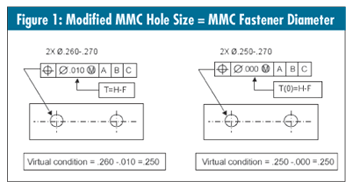
As an example, let's assume a hole diameter of .260 - .270 (all figures in inches) and a fastener diameter of .250. Both H and F will be the MMC value of the respective features. So, H (.260) - F (.250) = T (.010). The problem with this method is that holes less than .260 (down to .250) aren't allowed regardless of their location.
Now this is where zero is more. We're going to modify the formula slightly to read T(0) = H - F. Now we have a value of zero that the MMC hole minus the MMC fastener must satisfy: H(.250) - F(.250) =T(0).
In other words, we have modified the MMC hole size to equal the MMC fastener diameter. The new hole size is a .250 - .270 diameter, and the location tolerance is zero at MMC. Virtual condition remains unchanged. (See the example in figure 1.)

As you can see, the change to zero tolerance isn't difficult. This little change allows acceptance of the full range of parts that will assemble and meet the hole size and location tolerance.
Virtual condition remains unchanged for both methods. Caution: Do not apply regardless of feature size with zero tolerance. Remember, all the tolerance comes from the bonus, and with no bonus you get no tolerance at all.
Manufacturing may not warm up to this idea right away, but when they achieve greater tolerance with this method, they should come around and may even request it.
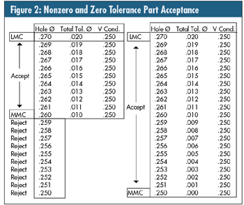
In the example seen in figure 2, for the nonzero toleranced part (left side of graphic), the range of acceptance falls off at the MMC hole size, which is far short of the virtual condition. Any hole size less than .260, regardless of its location, should be rejected.

The range for the zero tolerance part (right side of the graphic) is equal to the virtual condition and will allow acceptance of all parts that meet the hole size and location requirements.
When using functional gaging (ASME Y14.43) designed for verification based on virtual condition (absolute policy), the use of zero tolerance on the workpiece is the preferred combination.
If a virtual condition functional gage is used with the toleranced method, the gage will accept parts with holes smaller than the specified MMC, provided that they're located within the acceptable location. These are parts that would have been rejected, based on size check, per the drawing.
There are circumstances where this method is not necessarily the best choice. However, for most conventional assemblies zero tolerancing will work well.
If you want to do more with less, try doing the most with nothing (zero, that is).
James Keith is a member of the ASME Y14.5 Standards Committee, and a consultant and instructor with Crucial Knowledge (www.crucial-knowledge.info), based in Wichita, Kansas.
|