| by Ken Woodbine
Inspecting workpieces dimensionally to ensure conformity to design criteria is an integral part of manufacturing. Problems can arise, however, when the design intent is translated into a set of inspection instructions. This process usually requires a series of difficult, time-consuming and potentially inefficient operations with numerous opportunities for error and misinterpretation. The solution lies in a paperless inspection plan that can be used to create inspection routines without need for a traditional blueprint.
An inspection plan defines measurement and inspection requirements. It’s used in conjunction with measurement and inspection software to create a part inspection program on a measurement device. However, the medium for conveying the part inspection information is often a marked-up blueprint with hand-drawn annotations indicating the datums to use, features to inspect and tolerances to apply. Not only is the inspection plan created manually, but entering this information into the inspection software must also be done by hand, requiring hours at the inspection device. Often the part itself must be placed on the inspection device, and the program must be developed on the machine. This keeps the inspection device and its operator from performing the value-added services of measurement and inspection.
As part of the process of improving inspection planning and increasing efficiency in part programming, some developers have improved measurement and inspection software. For example, they’ve included preprogrammed inspection routines and made software more intuitive so its data-gathering and analytical capabilities are accessible by a larger number of operators. Also, working with a CAD file in the part inspection software improves efficiency when creating part programs.
Although these improvements solve one problem, they don’t address the need for a paperless methodology that will efficiently move inspection plan information from the design environment to the final inspection device. A more comprehensive approach is to house the inspection planning function in the CAD system itself.
Two reasons support this choice. First, because a definitive link exists between design intent and manufacturability, the CAD system--which is where the part design is created--is the most logical place to develop an inspection plan. Second, engineers responsible for part design are most familiar with the particular CAD system they use on a daily basis and less familiar with measurement and inspection software programs. Thus, when the inspection planning process is placed in the CAD system, an engineer can include the inspection plan as an integral part of the design. This ensures a seamless flow of metrology information from design through production and inspection, and provides a direct conduit between design intent and inspection.

The critical link between design and manufacturing can’t be overstated. These days, enlightened quality control focuses not on products coming off the production line but on the manufacturing process itself. This ensures each operation is functioning in an optimum way. For decades, dimensional measuring has served as the foundation for the statistical analysis that sets up, validates and maintains manufacturing integrity. Integrating this data with the manufacturing process provides close to real-time knowledge of part and process health as well as guidance for process control and improvement. It not only eliminates scrap and optimizes equipment use, personnel and material, but it also puts responsibility for quality into the hands of the people who make the product.
The same reasoning can be applied to developing the inspection plan in the CAD system. This vital function is placed in the hands of the people who design the product and are in the best position to create a plan that ensures the control of key part features during the manufacturing process.
A design engineer doesn’t need detailed knowledge of inspection technology or inspection equipment, just a list of features critical to dimensional control. A datum and tolerances can be established, and the operation to which they apply indicated in the plan. The engineer does not need to know on what type of equipment the inspection operation will be fulfilled. It can be conducted on a CMM, a vision system or a machine tool using an onboard probe; whatever inspection tool is used, the inspection plan will embody the necessary information to complete the job.
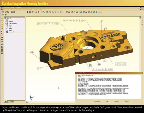
Wilcox Associates, developers of PC-DMIS metrology software, has recently introduced PC-DMIS Inspection Planner, which is comprised of two distinct modules. The first is the IP Planner, an add-on software module to existing CAD systems. The IP Planner allows design engineers to use the CAD system to define an inspection plan, which will contain all the information relevant to inspecting the component. The IP Planner effectively creates a virtual, marked-up blueprint of the part, defining each feature to be inspected and the method for inspecting it. It allows the engineer to define data, dimensions and the necessary metrological relationships among features. All this is accomplished using a set of integrated tools tailored for the specific CAD system. The Inspection Planner module is currently available for SolidWorks and Unigraphics, and several other CAD systems are on the way.
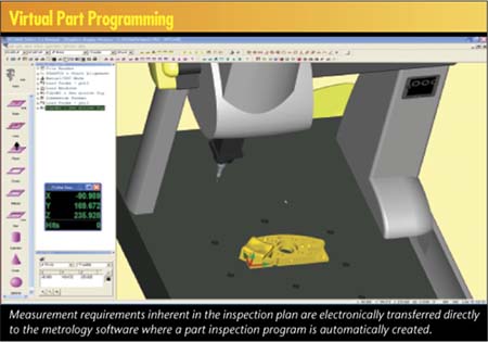
The second piece of the Inspection Planner suite is the IP Measure module. Where the IP Planner module creates the inspection plan, the IP Measure module puts it to maximum use by automatically creating a part inspection program on the targeted metrology device. The measurement requirements inherent in the inspection plan are transferred directly to the measurement software, where a part program is then automatically created, the probing path optimized and the entire routine checked with collision-avoidance algorithms before it’s executed on the physical inspection device. The process is direct and paperless. Because the plan is conveyed electronically, there’s no chance of losing or misconstruing design intent in the process.
For example, CMM operators and programmers can use PC-DMIS software to automatically generate part programs from Inspection Planner files. The time needed to build a part program using this approach is a fraction of what’s required using conventional methods because programmers don’t need to manually input motion or measurement commands or reams of information from paper blueprints into their inspection routines. This approach vastly minimizes the opportunity for introducing programming errors.
PC-DMIS software includes a virtual-part programming environment that doesn’t require the CMM or any other inspection device--or even the part itself. The operator can simulate the entire part programming environment, including the machine, probe, part and fixture setup, using 3-D animation tools.

Because inspection requirements and CAD models are combined into a single associated entity, changes in the CAD model automatically generate changes in the inspection plan. Subsequently, a change in the inspection plan is automatically converted to an update of the original part inspection routine. This solves a major problem in managing design change by eliminating communication slipups to production or the quality department--oversights that often create manufacturing aberrations. With so much of the production process outsourced, the ability to create an inspection plan at the design source and have it automatically updated with each design change helps eliminate version control problems. Because the design change flows seamlessly into the original part-inspection program, the danger of a mismatch between the CAD design and the part program is minimized.
Many CAD systems now have geometric dimensioning and tolerancing functionality built into the modeling environment, which is another advantage of using the CAD system to create an inspection plan. GD&T is a standardized language of symbols and concepts that allows a designer to describe parts and part features in a precise and logical way. GD&T provides the geometric definition of part and feature size, shape, location and orientation. The shape and tolerance determine the limits of production variability.
There are seven shapes, called geometric elements, used to define a part and its features. There are also certain geometric characteristics that determine the condition of parts and the relationship of features such as straightness, flatness, profile, parallelism, position, total runout and others. These symbols form a common language everyone can understand. With CAD-integrated inspection planning, GD&T symbols can be easily converted into inspection plan commands that form the basis of the subsequent part program.
What’s in the future for CAD-integrated inspection planning? One important area now being studied is a methodology for closing the loop between the plan and the actual inspection operation by populating the model with the inspection results. This is particularly important in the early stages of production, where more engineering oversight is involved. Ostensibly, the engineering department could have immediate feedback in the design tool, illustrating how closely the manufacturing process is conforming to design intent.
Managing the inspection plan of parts from a CAD system eliminates a major source of inefficiency and significantly reduces part programming time. It has the potential to foster a new era in precision process control, resulting in improved manufacturing quality.
Ken Woodbine, Wilcox Associates’ vice president of sales and marketing, has been involved in the metrology industry for 18 years and has been a driving force behind the evolution of the EMS philosophy.
Founded in 1987, Wilcox Associates Inc. is the developer of PC-DMIS, the world’s leading CMM software, and Enterprise Metrology Solutions, a tightly integrated suite of software products focused on the collection, evaluation, management and presentation of manufacturing data.
|