| by Paul Lomax
Many of the materials used
in today’s products have some sort of coating, whether
it’s the shiny new paint job on your Lexus, the anodized
protection on some of its parts or the gold plating on the
contacts in its electrical system. For reasons of economy
or functionality, the thickness of these coatings must be
accurately measured to ensure parts perform as required
or that material (e.g., gold) isn’t being used unnecessarily,
driving up product costs.
Over the years, a variety of equipment has been developed
to help manufacturers monitor and control the thickness
of coatings. Most of these tests are nondestructive and
cover a wide range of coating thickness and material.
What follows is a brief explanation of the various coating
thickness technologies and their likely applications. Specific
applications require specific instruments. For example,
liquid or powder coating on an automotive part, anodize
over aluminum, gold on a printed circuit board, or paint
thickness on an outdoor structure such as a bridge or water
tank all require instruments that use certain test measurement
methods. A basic understanding of these methods is essential
in selecting the appropriate unit.
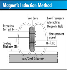 This
technology measures nonmagnetic coatings over ferrous substrates
and magnetic coatings over nonmagnetic substrates. When
the probe is positioned on the sample, the linear distance
between the probe tip that contacts the surface and the
base substrate is measured. This
technology measures nonmagnetic coatings over ferrous substrates
and magnetic coatings over nonmagnetic substrates. When
the probe is positioned on the sample, the linear distance
between the probe tip that contacts the surface and the
base substrate is measured.
Inside the measurement probe is a coil that generates
a changing magnetic field. When the probe is placed on the
sample, the magnetic flux density of this field is altered
by the thickness of a magnetic coating or the presence of
a magnetic substrate. The change in magnetic inductance
is measured by a secondary coil on the probe. The output
of the secondary coil is transferred to a microprocessor,
where it’s viewed as a coating thickness measurement
on a digital display.
This method is quick and can be used with either a bench
top or hand-held coating thickness gage. Common applications
include liquid or powder coatings, as well as platings such
as chrome, zinc, cadmium or phosphate over steel or iron
substrates.
Factors such as the part’s geometry and the coating’s
thickness determine whether the magnetic inductive method
is the proper approach. Typically, coatings such as paint
or powder greater than 0.1 ml can be measured using this
method.
With the magnetic induction method, users should keep
in mind that an erroneous reading could occur when measuring
a coating such as nickel over steel. Because nickel is partially
magnetic, a magnetic inductive probe won’t read this
coating correctly. To do so, a phase-sensitive eddy current
method is used instead.
A top coat with a zinc galvanize over steel is another
typical application. Users should be aware that with a magnetic
inductive probe, the thickness reading will equal the total
thickness over both the top coat and the zinc galvanize.
Different equipment is used to measure each coating separately.
With this method, as with most measurement methods, it’s
often necessary to calibrate the instrument on a bare, uncoated
substrate. However, some newer instruments have the capability
to detect the substrate material through the coating and
calibrate themselves accordingly. This is useful when measuring
a sample for which the substrate is unknown and a bare substrate
is unavailable.
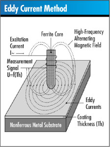 This
method measures nonconductive coatings on nonferrous conductive
substrates, nonferrous conductive coatings on nonconductive
substrates and some nonferrous metal coatings on nonferrous
metals. Eddy current measuring is similar to the magnetic
inductive method previously mentioned. It even uses many
of the same probe designs. This
method measures nonconductive coatings on nonferrous conductive
substrates, nonferrous conductive coatings on nonconductive
substrates and some nonferrous metal coatings on nonferrous
metals. Eddy current measuring is similar to the magnetic
inductive method previously mentioned. It even uses many
of the same probe designs.
As with a magnetic induction probe, the eddy current method
also contains a coil. In this case the coil has the dual
function of excitation and measurement. This probe coil
is driven by a high-frequency oscillator to generate an
alternating high-frequency field. When near a metallic conductor,
eddy currents are generated in the conductive material.
This causes an impedance change in the probe coil. The distance
between the probe coil and the conductive substrate material
determines the amount of impedance change, which can be
measured, correlated to a coating thickness and displayed
in the form of a digital reading. Common applications include
liquid or powder coating over aluminum and nonmagnetic stainless
steel, and anodize over aluminum.
As with the magnetic inductive method, the eddy current
method’s reliability depends on the part’s geometry
as well as the coating’s thickness. Users should know
the base substrate prior to taking a reading. An eddy current
probe shouldn’t be used for measuring a nonmagnetic
coating over a magnetic substrate such as steel. Neither
is this method reliable for measurements of nickel over
aluminum.
In cases where users must measure coatings over magnetic
or nonferrous conductive substrates--such as in a job shop--they’d
be best served with a dual magnetic induction/eddy current
gage that automatically recognizes the substrate.
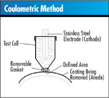 This
measurement technology is a destructive testing methodology
that has many important functions. Measuring the duplex
nickel coatings in the automotive segment is one of its
more significant applications. With the coulometric method,
the weight of an area of known size on a metallic coating
is determined through localized anodic stripping of the
coating. The mass-per-unit area of the coating thickness
is then calculated. The coating’s measurement is made
using an electrolysis cell, which is filled with an electrolyte
specifically selected to strip the particular coating. A
constant current runs through the test cell, and because
the coating material serves as the anode, it gets de plated.
The current density and the surface area are constant, and
thus the coating thickness is proportional to the time it
takes to strip the coating. This method is particularly
useful for measuring electrically conductive coatings on
a conductive substrate. This
measurement technology is a destructive testing methodology
that has many important functions. Measuring the duplex
nickel coatings in the automotive segment is one of its
more significant applications. With the coulometric method,
the weight of an area of known size on a metallic coating
is determined through localized anodic stripping of the
coating. The mass-per-unit area of the coating thickness
is then calculated. The coating’s measurement is made
using an electrolysis cell, which is filled with an electrolyte
specifically selected to strip the particular coating. A
constant current runs through the test cell, and because
the coating material serves as the anode, it gets de plated.
The current density and the surface area are constant, and
thus the coating thickness is proportional to the time it
takes to strip the coating. This method is particularly
useful for measuring electrically conductive coatings on
a conductive substrate.
The method can also be used for determining the coating
thickness of more than one layer on a sample. For example,
the thickness of nickel and copper can be measured on a
part with a top coating of nickel and an intermediate copper
coating on a steel substrate. Another example of a multilayer
coating is chrome over nickel over copper on top of a plastic
substrate. Coulometric testing is commonly used in electroplating
plants with a small number of random samples.
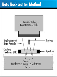 This
method begins when a test sample is exposed to beta particles
from a beta-emitting isotope. A beam of beta particles is
directed through an aperture onto the coated component,
and a proportion of these particles are “backscattered”
from the coating through the aperture to penetrate the very
thin window of a Geiger Muller tube. The gas of the GM tube
ionizes, causing a momentary discharge across the GM tube
electrodes. The discharge--in the form of a pulse--is counted
and then translated into coating thickness. This
method begins when a test sample is exposed to beta particles
from a beta-emitting isotope. A beam of beta particles is
directed through an aperture onto the coated component,
and a proportion of these particles are “backscattered”
from the coating through the aperture to penetrate the very
thin window of a Geiger Muller tube. The gas of the GM tube
ionizes, causing a momentary discharge across the GM tube
electrodes. The discharge--in the form of a pulse--is counted
and then translated into coating thickness.
Materials with low atomic numbers backscatter the beta
particles at a significantly lower rate than materials with
high atomic numbers. For a sample with copper as a substrate
and a gold coating of 40 µm, beta particles are scattered
by both the substrate and the coating material. If the gold
coating thickness increases, so does the backscatter rate.
The change in the rate of particles scattered is therefore
a measure of the coating thickness. Reliable applications
for the beta backscatter method are measurements where the
atomic number of the coating and substrate differ by 20
percent. These include gold, silver or tin on electronic
components as well as coatings on machine tools, decorative
plating on plumbing fixtures, and vapor-deposited coatings
on electronic components, ceramics and glass. Other applications
could include organic coatings such as oil or lubricant
over metals.
The beta backscatter method is useful for thicker coatings
and for coating/substrate combinations where magnetic induction
or eddy current methods won’t work. It’s also
less costly than the X-ray fluorescence method.
Changes in alloys affect the beta backscatter method,
and different isotopes and multiple calibrations might be
required to compensate. An example would be tin/lead over
copper, or tin over phosphorous/bronze. Both applications
are typical in printed circuit boards or contact pins, and
in these cases the changes in alloys would be better measured
with the X-ray fluorescence method.
 X-ray
fluorescence is a versatile, noncontact method that allows
the measurement of very thin multilayer alloy coatings on
small parts and complex shapes. X-ray
fluorescence is a versatile, noncontact method that allows
the measurement of very thin multilayer alloy coatings on
small parts and complex shapes.
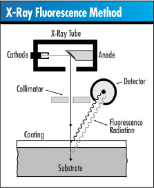
Measurement is performed by exposing the part to X-radiation.
A collimator focuses the X-rays onto an exactly defined
area of the test specimen. This X-radiation causes characteristic
X-ray emission (i.e., fluorescence) from both the coating
and the substrate materials of the test specimen. This characteristic
X-ray emission is detected with an energy dispersive detector.
Using the appropriate electronics, it’s possible to
register only the X-ray emission from the coating material
or substrate. It’s also possible to selectively detect
a specific coating when intermediate layers are present.
Common applications include printed circuit boards, electronic
components, jewelry and optical components.
X-ray fluorescence isn’t used to measure organic
coatings. It’s also somewhat limited by the coating’s
thickness, usually not exceeding 0.5-0.8 mils. However,
unlike the beta backscatter method, X-ray fluorescence can
measure coatings with similar atomic numbers, such as nickel
over copper. Different geometrical parts can also be measured
with this method.
As previously mentioned, different alloys affect an instrument’s
calibration. Analyzing base material as well as the coating’s
thickness is critical to ensure precision readings. A state-of-the-art
X-ray system and software program will reduce the need for
multiple calibrations, save time and improve quality.
These gages typically operate using the magnetic induction
method, the eddy current method or a combination of both.
In today’s economy, many manufacturing companies have
multiple applications; therefore, selecting the right gage
to meet multiple tasks is critical. Hand-held gages come
with either built-in integrated probes or units with probes
on a cable. These units are ideal for one-hand operation
and are most often used on a larger measurement surface
such as an automobile part or appliance. Units that have
detachable probes offer more flexibility, and they also
allow users to exchange probes in the future if the application
should change.
Many hand-held units also have complete statistical capabilities--including
instant averaging, high/low and standard deviation--that
can be downloaded to a computer for detailed process control.
Some units will even take readings and immediately send
the measured values to a computer via a wireless radio transmitter.
In those cases, operators don’t have to wait until
the end of a shift or lot to download the stored readings.
Access to the data is immediate.
Influences in coating thickness measurement can affect
the accuracy of the reading, and users should be aware of
these when taking measurements. Some of these influences
include distance to the edge of the part, surface curvature,
thickness and magnetic properties of the substrate, heat
treatment, magnetic particles in the coating material, external
magnetic fields and residual magnetism, surface roughness
and contact force (i.e., probe pressure).
A corrective calibration can be established by taking
readings of certified foils on the actual substrate that
will be in use. This calibration can then be stored so that
users don’t have to recalibrate for every part. If
a gage offers this capability, users can press a button
to select the application that represents the specific calibration.
Some gages can calibrate through the coating.
Comparisons have been made between probes that require
calibration for curvature and new curvature-compensated
probes. Special probe designs virtually eliminate curvature
dependence and improve the accuracy of the readings. This
in turn makes it possible to measure the coatings on differently
shaped surfaces without having to constantly recalibrate
to a specific part geometry.
There are several different types of measurement methods
and a wide variety of gages, both hand-held and bench top,
from which to choose. Knowing some of the benefits and limitations
of each method is important when deciding which unit will
be most suitable.
Paul Lomax is the director of marketing for Fischer
Technology. He has more than 13 years’ experience
working with coating thickness measurement and related testing
instruments and accessories.
Since 1953, Fischer instruments have set the global
standard of excellence for coating/plating thickness. Helmut
Fischer GmbH has been the leading innovator of coating thickness
measurement equipment, with 40 patents and the widest and
most precise product offerings available. The Fischer product
line includes hand-held, bench top and laboratory units
that incorporate magnetic induction, eddy current, coulometric,
beta backscatter and X-ray fluorescence test methods. Visit
their web site at www.fischer-technology.com
|