| by William A. Keely
Eddy current inspection technology has been used for years to inspect parts for variations in materials hardness, materials chemistry and part geometry. At its most basic, this type of inspection is a noncontact means of part evaluation and uses comparison techniques to evaluate parts. The eddy current signature of a known good sample is compared to the signature of a part under inspection. If these signatures match within set limits, the part is considered good and passes; otherwise, it fails.
Strictly speaking, a part's noncontact eddy current signature is a measure of the conductivity of the material adjacent to the eddy current probe. To assist users in understanding what actually occurs during eddy current evaluation, this conductivity parameter can be subdivided into the chemistry, hardness, geometry and temperature of the part's base material because all these parameters directly affect the material's conductivity. In most cases, temperature remains relatively constant during the inspection, so it can usually be dropped from a sort equation and won't contribute adversely to readings taken from the parts. However, in instances where there's a significant temperature difference between what's used as the "master" part and the parts under test, temperature should be considered a variable that must be dealt with during the sort.
Because a part's eddy current signature represents all the parameters that are simultaneously extracted from the part, in instances where part geometry--i.e., the dimensional characteristics of the part--is the only parameter of interest, it becomes difficult to isolate the portion of the signature associated with this single part parameter. Precise dimensional measurements using noncontact eddy current techniques have therefore been challenging, if not impossible, to make.
As a result, it's not been possible to use this technology effectively for dimensional gaging. In fact, from the standpoint of dimensional measurements, the best that noncontact eddy current inspection has been able to achieve is about ± 0.005 in. This isn't accurate enough for specifications such as bore diameters, where the measurements must be accomplished to within a few microns. This shortcoming in noncontact eddy inspection has relegated the technology to gross inspections such as detecting the presence of threads rather then precisely gaging hole diameters.
Recently, however, the technology has been used successfully in dimensional gaging where the signature extracted from the part represents only part geometry, with no signature contamination from the chemistry, hardness or temperature of the base material. This has been accomplished using a unique probe called the Ball Runner developed by NDT Technologies Inc. This probe allows a part's eddy current signature to be converted from one that includes all four of the sensed part parameters to a signature that considers geometric information only. The probe is capable of making gage measurements down to the micron level and can accomplish this, dynamically, at a rate of about three inches per second.
Here's how the new technology works. If an eddy current sensor is designed so that it reads a target's signature rather than a part's, and if the chemistry and hardness of the target don't change, then the target's absolute position with respect to the eddy current sensor can be precisely determined. Linking this target to a device used to detect dimensions of interest on the part means the target's eddy current signature, with respect to the sensor, will accurately represent the dimension that's being measured. This technique has reliably produced gage measurements into the micron range. Eddy current technology has finally crossed over from noncontact comparison inspection to contact gage applications.
If the probe used to gage the part is moved along or within the part, and the reading from the eddy current sensor is recorded and referenced to the probe's position with respect to the part, a profile of the area of interest can be recorded and reproduced on a Cartesian coordinate system. The profile can then be graphed. Limits can also be set around the profile so that a pass/fail decision about the part's dimensional characteristics can be made. Further, if the probe is passed through or over a gage as it enters or passes over the part, an absolute calibration of that gage profile can be recorded and stored along with the part profile itself. If this gage is traceable to NIST or another calibration standard, it can serve two purposes. First, the measurements from this gage can be used to calibrate measurements taken from the part. Second, the gage profile can provide traceability to NIST so that the measurement taken from the part can be qualified.
A profiling act-ivity of this type can usually be accomplished at rates up to several inches per second while yielding accuracies that range into the micron level. When compared to coordinate measuring machine (CMM) systems that take several minutes to gage a bore, these hybrid eddy current sensors will prove more efficient every time. Also, this measurement technique yields a continuous graph rather then a collection of points used to represent the part's absolute dimensions.
This technique's accuracy can also help save time with other measurements. For example, if the probe is rotated as it's extracted from a bore, and the probe's rotational position within the bore is recorded along with the probe's linear position, then bore ovality, cylindricity, taper and surface finish can be recorded simultaneously. This additional utility makes it easy for an entire bore to be mapped, opened and displayed as a surface on a computer screen. Using software that supports dimensional gages, users can zoom into any portion of the surface and view it as a 3-D model. The model can be compared directly to the prints that were originally used to create the part, thereby ensuring accuracy in the entire manufacturing process.
Supporting statistical software can be used to assist users in setting up the system properly to perform a sort. Typically, the software prompts users to cycle a number of known good parts through the system. The software then calculates the mean profile from this population along with its three-sigma limits. The result is a graph showing the mean or average profile and its calculated statistical variations.
If the graph from these known good parts represents the cross section of a typical manufactured "lot" of parts, it can hold much invaluable information. For instance, by studying the calculated three-sigma limits, users can begin to understand where variations in the manufacturing process occur. This information can be saved and the absolute variations in the manufacturing process compared to similar information taken from other manufacturing lots. If the limits change significantly, a review of the manufacturing process might be in order.
Because the dimensional information extracted from parts is based on the position of a target with respect to an eddy current sensor--as opposed to the eddy current characteristics of the part itself--this approach to dimensional measurement can be used to gage any material, including plastics and ceramics.
Typically, the calculated three-sigma limits from the learned parts establish the limits within which all other good parts should fall. If the parts under inspection have profiles that fall outside these limits, either the limits calculated during the learn are too tight, or the part whose profile falls outside these limits is out of spec.
When these systems are put into service, users typically proceed as follows:
• A number of known good parts (usually 10) are learned by the system. These should represent whatever typical manufacturing variations can be expected during the normal manufacturing process.
• The software calculates the average profile and the three-sigma limits of the population distribution of profiles, and displays these on the computer screen as two green lines.
• Users then run known bad parts through the system and verify that they do, in fact, fail the inspection. These parts become the "bad rabbits."
• When the system is in use, operators need only to cycle the bad rabbits through the system and verify that they fail to qualify system operation.
The potential applications of this technology are endless. A few of these are discussed below.
• Profiling gun bores. This technology offers substantial capabilities for profiling pistol, rifle and large-caliber artillery bores. Probes can easily be manufactured so that they're of any length and diameter, from 0.150 in. to several inches, if required. Further, given the technology's capability to make reliable measurements down to the micron level, it can be used to perform a gage measurement on the bore and record the measurement as a dynamic profile in a digital format. Thereafter, when the weapon is fired, the technology can also perform a reverse profile on the projectile. This allows the bore's profile and the projectile to be correlated so that proof of the projectile's origin can be established.
In addition, the entire bore can be profiled to inspect the characteristics of its rifling. After the bore's profile has been recorded, the system software can be used to open the bore so that its interior is shown as a 3-D model on the screen. Limits can then be placed around this profile to determine if the bore is within spec. The software allows the bore profile to be sectioned so that any portion of this 3-D bore can be viewed as a 2-D cross section. This cross section can then be manipulated to allow viewing and measuring of any portion of the bore.
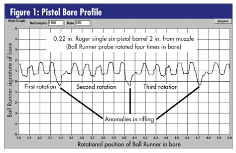
A system of this type can also measure bore wear after the weapon has been fired a number of times. A bore profile in its "as manufactured" condition can be stored and, using an overlay process, compared to the same bore after the weapon has been repeatedly fired (as seen in figure 1). This comparison will yield information about the degradation of the bore caused by the firing events it was exposed to. Additional software, still under development, would allow bore wear not only to be predicted but also superimposed on the profile so that it can be viewed in a worn state.

• Run-out inspection. A run-out inspection of any cylindrical part can easily be accomplished by positioning a version of the probe, mechanized with a stylus-type contact, with the outer surface of a part and then rotating the part. The resulting signature will represent the part's roundness. If the probe is moved along the surface as the part is rotated, the part's outer ovality, cylinder dimension and taper can be measured. If the probe's linear position with respect to the part's outer surface is recorded along with the probe's linear position with respect to part data, the part's outer surface can then be represented on a three-coordinate matrix on the system screen. It should be noted that this type of inspection usually is accomplished with noncontact eddy current techniques, but these also detect changes in the chemistry and hardness of the base material along the surface of the part that's examined. These extraneous inputs will cause the noncontact systems to be somewhat inaccurate if absolute dimensions are to be measured, leading to false part rejects.
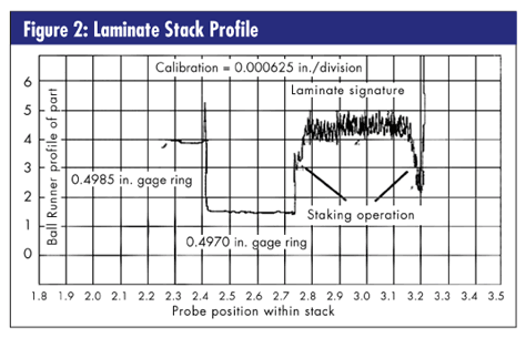
• Precision measurements of holes in laminate stacks. Precisely measuring holes in laminate stacks presents challenges for any measurement technique. Because laminate stack holes are noncontiguous, and the laminates' absolute alignment is one of the parameters that typically must be measured, even pin and plug gages have difficulty properly measuring the inside diameter of the bore. The Ball Runner probe, however, has no problem with noncontiguous holes and in fact excels in making precision measurements in holes created from separate pieces of material.
As shown in figure 2, the profile of the laminate stack depicts not only the individual laminates but also the presence of the swaging operation used to decrease the diameter of the last few laminates so that the stack can be properly pressed onto a shaft. It also allows the stack to be checked to ensure that it contains the correct number of laminates. This can be accomplished in two ways. First, the stack's width can be seen on the X-axis. This width varies directly with the number of laminates in the stack. Second, by counting the number of transitions of the laminate indications, the actual number of laminates in each stack can be counted.

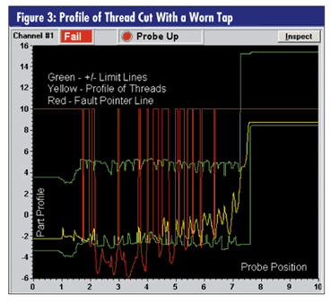
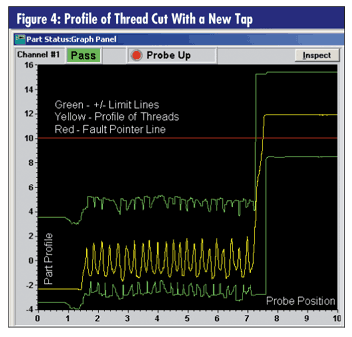
• Worn tap predictions . Taps used to thread holes are usually changed based on a calculated change cycle. This cycle relates to the type of material being tapped, the type of tap used, the tap speed, the type of coolant used and other parameters specific to the application. In reality, this calculation is only slightly better then an educated guess. A much better way to approach the problem is to use the probe to profile the threads after the tapping operation has taken place and set limits that relate to the thread characteristics created by a worn tap. As the tap wears, a measurement of the wear condition taken from the part that's actually being tapped can be fed back into the manufacturing process. By default, this feedback loop can eliminate scrap from a tap that's actually creating malformed threads. (See figures 3 and 4.)


Two excellent examples support this approach to scrap reduction. In one case, a tier one supplier to General Motors uses this technique to eliminate scrap in a sintered metal transmission part. In the second case, a division of GM uses this technique to reduce scrap in a screw-machine part within a fuel-delivery system. In both cases, this means of measuring the degradation of a tap has superseded periodic tap replacement based on a calculated replacement cycle.
William A. Keely has a bachelor's degree in electrical engineering from Lawrence University in Southfield, Michigan, and an MBA from Western Michigan University in Kalamazoo, Michigan. He started NDT Technologies in 1988 as a supplier of eddy current-based test equipment to the automobile industry. Since that time he and his son, Jim, now the company's president, have worked to move NDT Technologies aggressively into other niche test equipment markets, including dimensional gaging and materials chemistry evaluation. Keely has recently stepped down from the position of president in preparation for a long-awaited Colorado retirement.
|