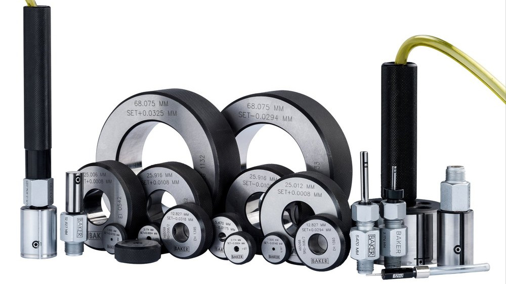
The jet in pneumatic dimensional (or air) gauging is the mechanical part of the sensing probe—air plug gauge, air ring gauge, air caliper gauge—through which compressed air is directed onto the part under measurement.
ADVERTISEMENT |
In its simplest form, we have two jets working in tandem facing in opposite directions (180°) to each other. Two are required to maintain a balance and to direct the air so that it impinges equally on the part surface. The back pressure created between the sensor and the part surface tells us whether the surface is farther away or nearer than required, i.e., whether the part is within its tolerance in comparison to a master part measured on the same equipment. The jets need to be central to the diameter. This is achieved by the jets’ placement in the body, which acts as guide. The central position is important to the accuracy of the gauge.
The jet needs to be protected against direct wear or damage due to accidental contact with external objects. Hence, they are recessed below the surface of the guide body.
Because the jets play a vital role in air gauging, the dimensional parameters of the jets are important for many reasons, including:
• The air that exits from both jets must be similar
• The air exiting the jet must not face any turbulence and must be directed normal to the surface of the probe body. That is, it must impinge at right angles to the surface to be gauged.
That’s why the bore size, length, geometry, and finish must be maintained. Additionally, if the jet is an insert, the jet’s inside diameter must be concentric to the outside diameter. This is important to maintain symmetric airflow with respect to the body. Also, the bore of the jet must have a fine finish to ensure a smooth and laminar airflow.
Next comes the placement of the jets in the guide body. If we’re talking about inserted jets (more on this later), the jet must sit perfectly in the seating bore meant for it—a mild interference fit. A fine film of adhesive like Loctite 386 helps. The seating diameters must be ensured so that while the jets are fitted they don’t lose their alignment and symmetry.
Not all air gauging systems use the same jet internal diameter (ID). The jet ID is based on the system air pressure, the air passages, and the control orifices; hence, there’s a definite relationship between the jet and the system (for example, the back pressure system, the null balance indication system, the differential system, or the piezo system). All are designed to support a particular jet size.
Also, there’s a relationship between the jet size and size of the part to be gauged. Larger jets can’t be used for smaller-diameter parts and vice versa. Each system has its own system pressure on which it works. So, there will always be limitations or advantages of one against the other.
Next comes the calibration of the system; this again depends on the jet. The air gauge readout unit and the jets on the air plug or air ring are, you may say, married to each other.
Many claim that their air gauge readout unit system is kind of universal; it will work with any jet size or with multiple jet sizes. This, however, isn’t really true when we’re looking to get the best accuracy. That’s impossible to achieve without adjusting the air pressure and flow. Air coming in and going out must be perfectly balanced and suited to the sensing device, because it will depend on the outflow. The linearity of air gauging depends on this, and one can’t make adjustments or corrections electronically to correct the linearity. Air coming out of 0.5 mm, 1.0 mm, 1.5 mm, or 2.0 mm jets can’t be the same under a constant system pressure that’s feeding the air gauge unit. It won’t create the right back pressure and still maintain linearity. Ideally, for every type of air gauge unit design, a particular jet ID is suitable or required to give the correct linearity and indication.
There are two methods of jet manufacture:
The first method is by inserting a separate jet having the required inside diameter into the sensor body, which itself is symmetric to the diameter of the air plug or the air ring. Then the jet is ground between centers to match the body diameter of the air plug or the air ring. After this, the jets are locally ground (recessed) as per requirement.
Pros: If something goes wrong, the jet can be removed and changed.
Cons: There are limitations when it comes to smaller diameters, or when one needs to put the jet closer to the face, e.g., in shallow bores.
The second method is that the jets are an integral part of the sensor body. That is, the jet is drilled directly into the body while maintaining symmetry. In this case, the jet must be formed either by a trepanning cutter or by grinding an air-escape slot to create a square jet. Then this is recessed by local grinding. It should be noted that integral jets are more difficult to create for air ring gauges.
Pros: This design is useful when diameters are small, or when the jet needs to be placed nearer to the face.
Cons: It’s difficult to drill smaller holes, particularly on larger diameters where the drilling length is longer. Smaller holes mean less airflow and, hence, limitation on the clearance and jet recession. The higher the length-to-drill diameter ratio, the more technically challenging it is to produce a good hole. Normally the ratio is 5:1.
Air gauging is by far one of the best gauging systems for bores when it comes to precision, reliability, and accuracy. The proper design and manufacture of jets is a key part of that performance.
Add new comment